
I2C Principles with Practical Examples

The post introduces the I2C communication protocol for embedded devices. It covers the principles of I2C, reading and writing data to devices, and it provides code snippets and practical examples for reading accelerometer data from the MPU6050 IMU sensor using Arduino or Raspberry Pi.
This is an old post that I wrote during my master's studies when I played a lot with microcontrollers.
Introduction
I2C (pronounced I-two-C) is a very popular communication protocol in the world of microcontrollers. Its advantage is that it allows communication between multiple devices by using only two wires, SDA (Serial Data Line) and SCL (Serial Clock Line), unlike USART or SPI, where every pair of devices needs its own set of wires. The protocol was invented by Phillips Semiconductors in 1982. The first time I encountered I2C was when I wanted to obtain the orientation in space with my Arduino. For that purpose, I bought an MPU6050 inertial measurement unit (IMU) that required I2C to get its sensor readings. At first, I was confused since I had no experience with digital communication protocols except a basic understanding of Arduino's Serial library. The first time I saw an example code for reading accelerometer and gyroscope data from the MPU6050, it scared me when I saw a bunch of hexadecimal register addresses and unfamiliar function calls. In this tutorial, I will try to do my best to explain the principle of the I2C protocol and show an example using an Arduino, a standalone ATmega328P chip, and a Raspberry Pi. I will start with an Arduino Uno and add examples with other devices later. I will use the MPU6050 IMU in my examples, but you may use whichever device you desire. Sometimes I will refer to the Arduino and the standalone ATmega328P chip, simply as ATmega328P, since this is also the processor that the Arduino uses, but I will also provide an example of how to use I2C on a standalone ATmega328P chip in plain C. On a side note, regarding legal issues, I2C can be freely implemented on any commercial device, but to use the name I2C on the product, you have to pay some money to NXP Semiconductor. For this reason, some of the products use a different name; for instance, Atmel calls it "Two-wire interface" (TWI) on their chips.
The Principle
To explain how the protocol works, I will use an example with three human slaves, where each one of them monitors a different sensor and reports the reading to one of the two masters when they request it. Slaves and masters use walkie-talkies to talk to each other. The image below shows the three slaves and two masters.
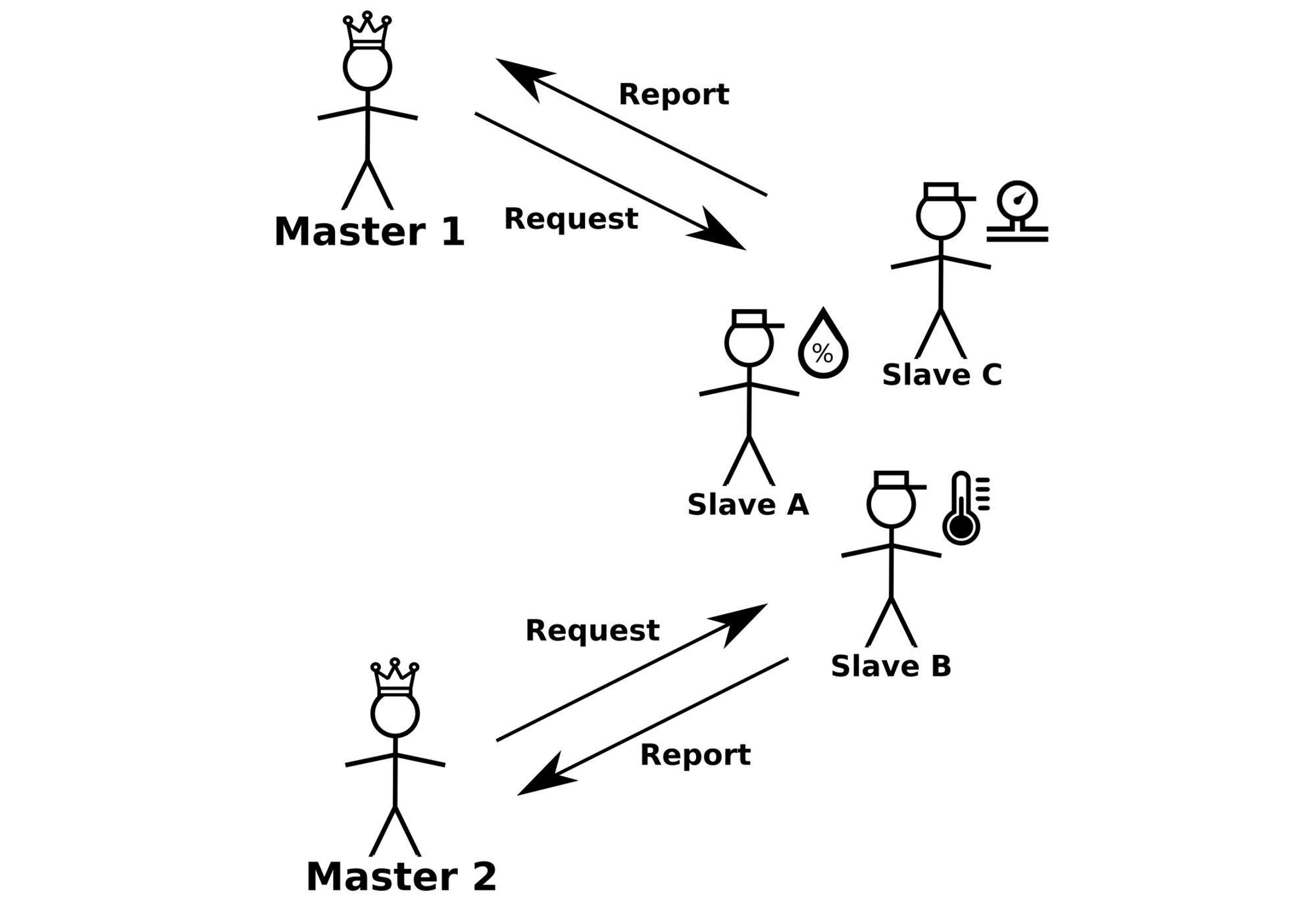
Slave A monitors a humidity sensor, slave B a thermometer, and slave C a barometer. Masters 1 or 2 can ask the slaves for readings whenever they want. In smaller microcontroller projects, you will most likely use a single master, but to explain the full functionality of I2C, I'm using two masters.
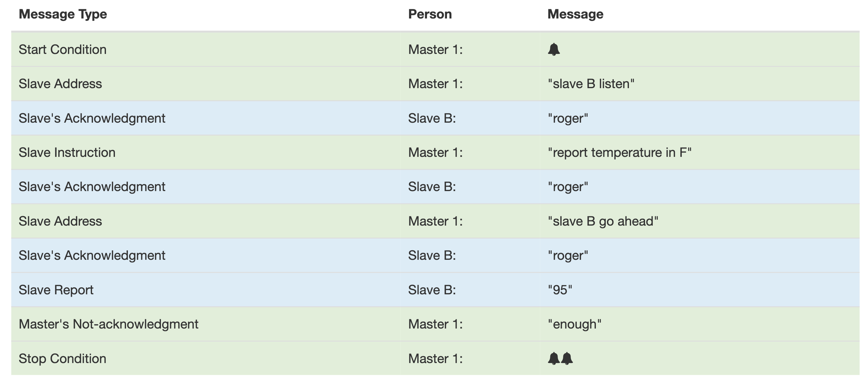
Since there are three different slaves, each one of them has a name (an address) by which a master gets their attention. To keep it simple, I will name them A, B, and C, as depicted in the image. They agreed in advance that to get the data from the slaves, a master has to first remotely ring a bell at the site where the slaves are, get the desired slave's attention by calling the slave's name, and then tell the slave in what units the data should be reported. Once the master gets a pencil and a piece of paper to write down the measurement from the slave, he transmits the name of the slave again, which means that the slave should report the measurement. Once the measurement is written down, the master rings the bell twice to mark the end of the conversation. Another important purpose of the bell is to let the other master know that he should wait until the first master ends the conversation. To ensure that a certain slave is present (better be) and that the instruction was heard, the receiver acknowledges that the instruction was received. If the master is happy with the received message, he transmits "enough" to indicate that this was all that was needed. I will call this "enough" as not-acknowledged (sounds weird, but you will see later why I call it like that). For the master 1 to receive the temperature in Fahrenheit from the slave B, the conversation would go as follows:
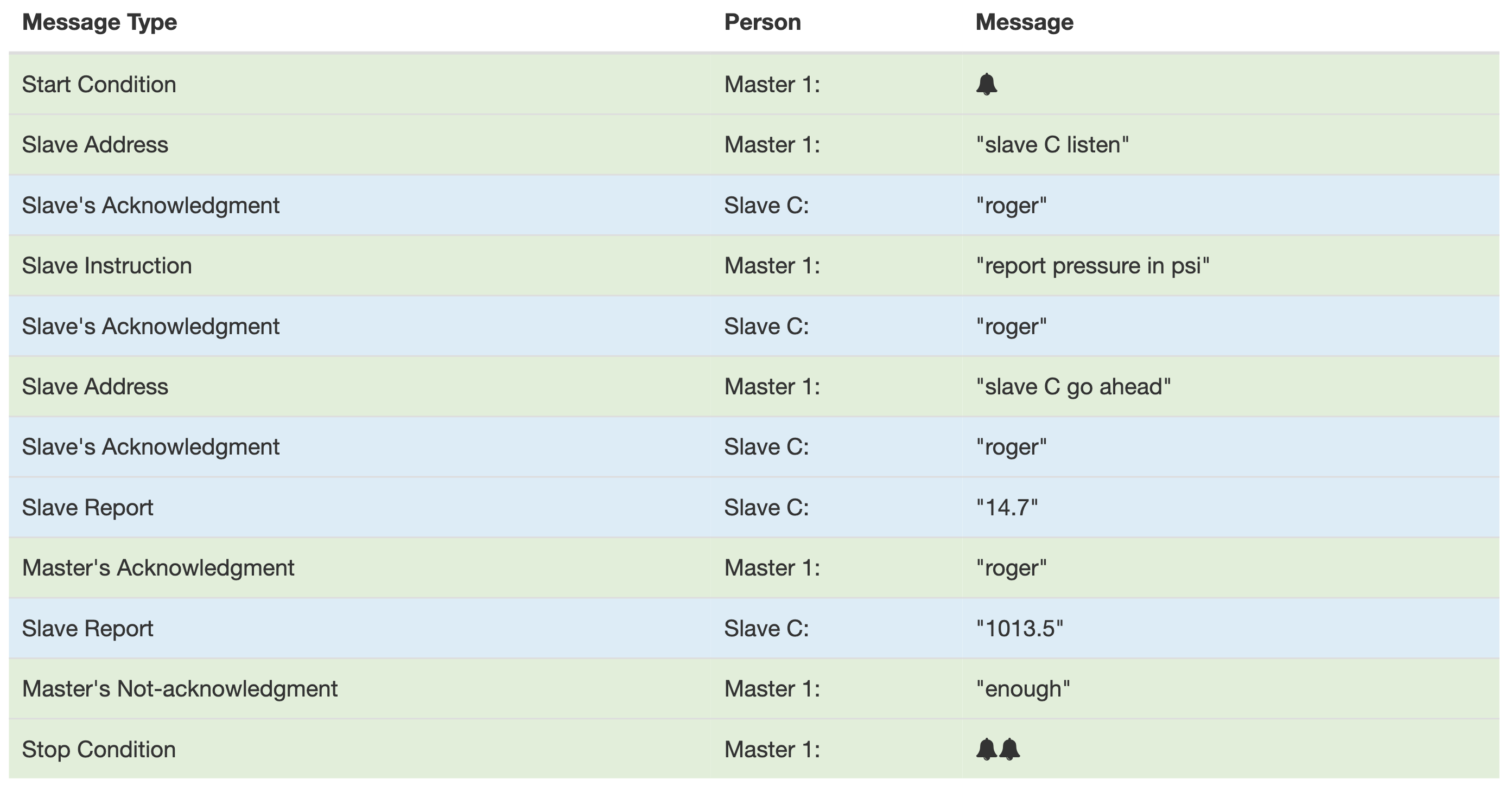
Just to understand another important concept, let's assume that master 1 wants to know the pressure in psi and MPa from slave C. They also agreed in advance that whenever the master acknowledges the reception by "roger", the slave then transmits the measurement in another unit right after. Slave C keeps track of pressure measurements in psi, MPa, atm, and torr, so if the master receives the measurement in psi, he acknowledges the message by "roger" to let the slave know to send the pressure in kPa as well. The slave keeps sending the measurement until the master "not-acknowledges" the reception as "enough" or until the slave has no more measurements to send. The conversation for receiving pressure measurements in psi and kPa would go like this:
This acknowledgment, not-acknowledgment agreement, would prove more useful if there were only one slave that was measuring all the different sensors at once. In that case, the master would tell the slave to report whatever measurement was the first on the list and keep acknowledging until all the required measurements were received. The communications seem pretty complicated and redundant, but this protocol is not intended for humans but for digital devices. By saying that they know something in advance", it implies that these are the protocol rules. Before going into the world of digital devices, let's review some of the specifications and prerequisites.
The Basics
To follow the tutorial, you should be familiar with the following:
- basic electronics
- basic C (or Arduino dialect)
- the difference between binary, decimal, hexadecimal,...
- what registers are (at least know that a register is a memory slot where data or instructions are stored, in ATmega328P, and other smaller I2C slave devices, registers hold 8 bits (1 byte)).
The devices communicating via I2C are all connected to the same set of wires, SDA (Serial Data Line) and SCL (Serial Clock Line). The two wires constitute the I2C bus. As shown in the example above, I2C is a multi-master, multi-slave protocol, which means that a system of nodes (devices) can have multiple master devices and multiple slave devices. To understand what this means, you need to understand what each of them does. In a few words:
- Master Device: generates the clock and initializes the communication with a slave device
- Slave Device: receives the clock and responds when addressed by the master.
Microcontrollers such as the Arduino (ATmega328P) can be configured to act as a master or a slave device, whereas simpler sensor devices usually support only the slave mode.
One thing to keep in mind when using multiple masters is that they cannot communicate with each other, but they have to listen to the I2C bus if anyone else is transmitting before requesting data from the slaves, so they don't request it at the same time, otherwise the slaves would not understand what masters want. This also applies to the regular conversation between people. If you talked to an audience, everyone who listened would understand what you are saying (assuming you talked loud and clear in a language everyone understood). But if everyone in the audience tried to tell you something at the same time, you would just hear some jibber jabber. If two or more masters transmit a packet to slaves at the same time, the packets collide, so in case of a multi-master I2C setup, a some sort of packet collision avoidance mechanism has to be implemented. As I wrote before, this only applies if you have a project consisting of multiple master devices, otherwise do not worry about this for now.
SCL and SDA
SDA is where the data, the payload, is transmitted between the devices.
SCL is where the master sends the generated clock signal that the slave devices receive. With this said, a shared clock between the master and slave devices makes I2C a synchronous protocol, unlike UART, which is asynchronous. In asynchronous protocols, the two devices talking to each other need to know the rate at which they will transfer the bits (baud rate).
The clock that the master generates defines the rate at which the data is transferred. I2C supports various clock speeds, but simple devices commonly used in microcontroller projects support the original 100 kHz mode or the 400 kHz fast-mode. The fastest supported mode for I2C right now is the 5 GHz Ultra Fast-mode.
Addressing
The number of devices that I2C can communicate with is defined by the number of bits each device's address consists of. I2C devices can have 7 or 10-bit addresses. Theoretically, the largest number that a 7-bit address can be is (1111111)2 or (127)10, which defines the maximum number of devices connected to the same I2C bus. Since some addresses are reserved and cannot be used for addressing, the maximum number of devices with 7-bit addresses is (112)10. (I am using the parentheses with a subscript to indicate the base of the number, so 2 for binary and 10 for decimal, and 16 for hexadecimal.) The maximum number of devices is also limited at the physical layer by the total bus capacitance.
I2C and any other memory addresses (registers, etc.) are expressed in hexadecimal by convention. Hexadecimal numbers are much more convenient than binary since binary addresses would become very long, which would be hard to remember and prone to mistakes. The conversion between hexadecimal and binary is much easier than between decimal and binary. Sometimes I will use the C-language syntax to indicate the base of the numbers, where decimal numbers are depicted simply as the number itself, binary numbers have a 0b prefix (ex: 0b1010 = 10), and hexadecimal have a 0x prefix (ex: 0xA = 0b1010 = 10).
Example with Digital Devices
To give more sense to what I have just explained, let's consider a real I2C example shown below.
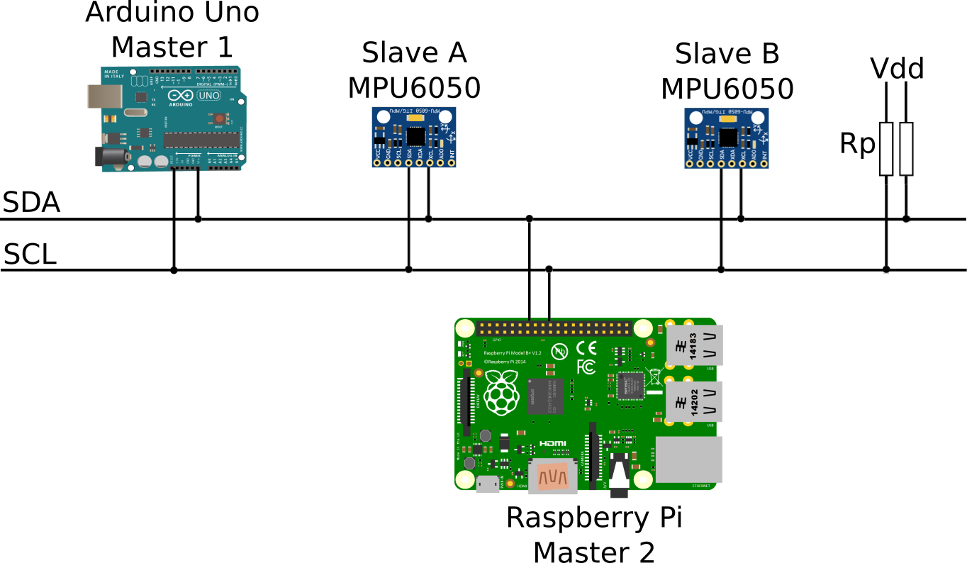
This setup uses two masters, one is an Arduino Uno used to control something, and the other one is a Raspberry Pi used for storing the data to a remote database. The slaves are two MPU6050 IMUs placed in two different spots on, for example, a spaceship.
As we switched from people to digital devices, the first thing to do is to wire them correctly. As you can see in the image above, both I2C wires, SDA and SCL, are connected to the same voltage source by two pull-up resistors. The pull-up resistors are used because the I2C lines are open-drain (or open-collector in TTL), meaning the signal can be pulled to low but not to high. For projects with Arduino, Raspberry Pi, and other similar devices, the voltage source is usually at 3.3 V or 5 V. The selection of pull-up resistors is a bit more complicated since an optimal resistance depends on the length of the wires and the number of devices connected to the bus. Sparkfun recommends starting with 4.7 kΩ resistors and working own if needed. All devices must be connected to a common ground, which is very important. Before getting all confused by selecting proper pull-up resistors, make sure that the devices you will use don't have them already; for instance, MPU6050 has both lines connected to high with 4.7 kΩ resistors. Having all the devices close to each other should work well most of the time, but if you intend to use longer wires between the devices, you might have to try different pull-up resistors. Also, remember that long wires are more prone to noise-induced errors, so if there is a lot of noise in the environment, the wires should be kept as short as possible.
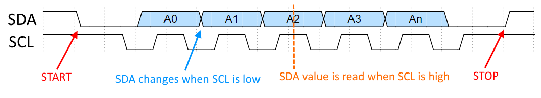
Now that all is hooked up, let's go into the protocol basics. The clock signal on the SCL is generated by the master devices when it initiates the communication. When no communication occurs, the SCL is constantly pulled to high. A very important rule of the protocol is that a signal on the SDA can change only when the clock is low; the only exception to this is when the master signals the start or the stop of the communication. Start and stop conditions consist of a change of state when the clock is high, and they are defined as:
- Start: SDA is pulled from high to low
- Stop: SDA is pulled low from high.
Right after the master transmits the start condition, other communication information follows. Devices decode whether the bit sent is true or false by checking if the voltage is high or low when the clock (SCL) is high. It's easier to explain this with a simple timing diagram, as shown below: (For drawing timing diagrams, I use WaveDrom.)
In this example, I will use devices with 7-bit addresses; slave A has the address (68)16, and slave B has the address (69)16. To address the right slave, its address has to be sent in binary right after the start bit. For example, to address the (68)16 MPU6050, (1101000)2 has to be sent.
Just like the master had to tell the slave whether to listen or to report the data, the master device has to do the same by sending another specific bit after the address. This bit is called the direction bit (READ/WRITE), where:
- Read: 1 (low)
- Write: 0 (high)
Sometimes the addresses are written as the write and read addresses. Those addresses are just the 7-bit device's address with the direction bit appended. Arduino's "Wire.h" library takes care of that for you, so you don't have to worry about it, but you might run into it at some point. For the (68)16 MPU6050, we could write, read and write addresses as follows:
- Read Address: (11010001)2 = (D1)16
- Write Address: (11010000)2 = (D0)16
When the slave is addressed and no errors occur, it acknowledges the message. The acknowledge bit is usually written as ACK and not-acknowledge as NACK, where:
- ACK: 0 (low)
- NACK: 1 (high)
The receiver device transmits ACK or NACK bit. It is transmitted right after the 8 bits from the sender are received. NACK bit is used to inform the sender that enough information was received and that the communication is about to stop or if an error occurred, so it can also be used for error checking.
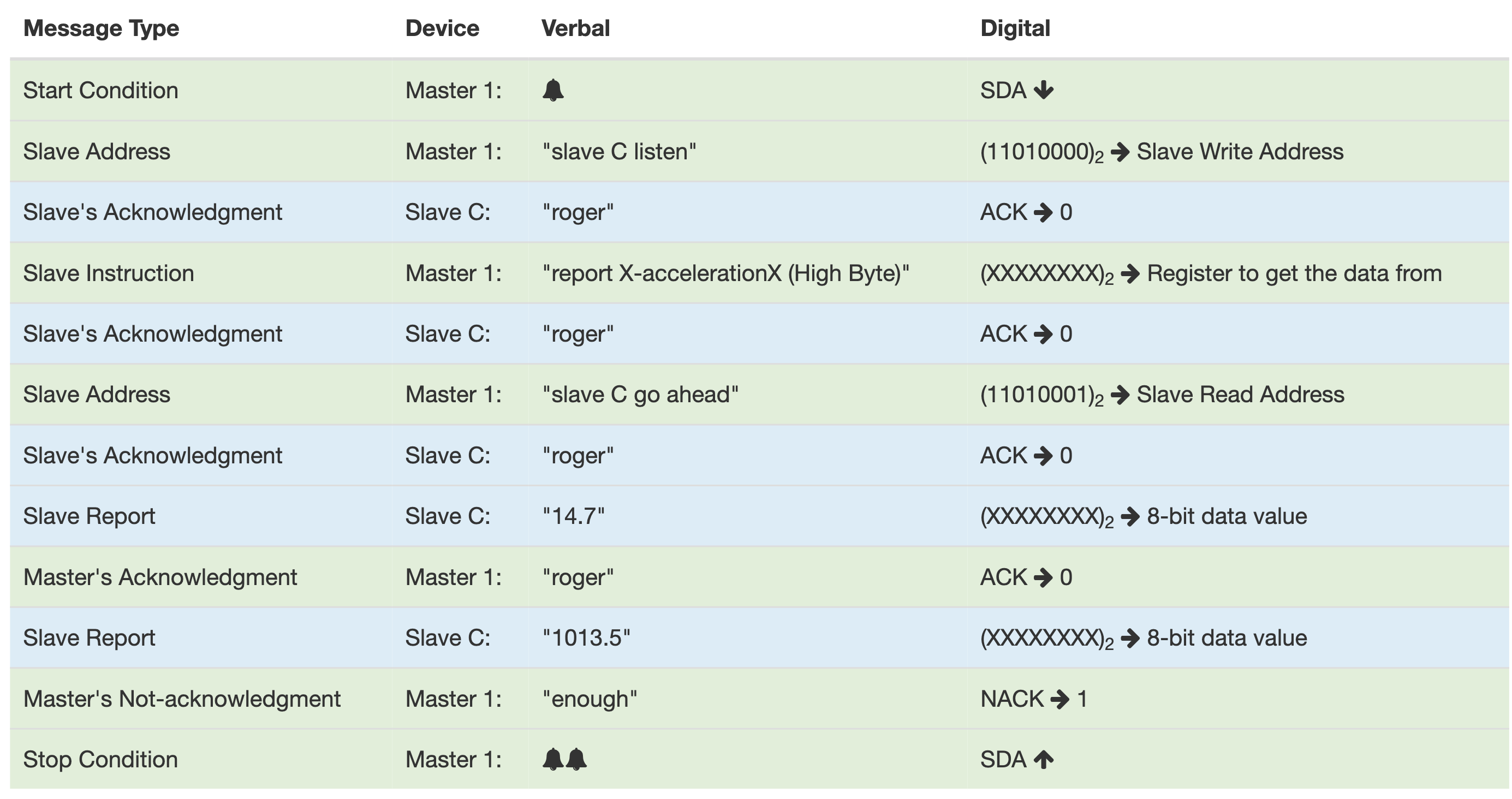
To recap how the whole communication between a master and a slave goes, I will show it in a similar table I used in the second example, except here I will use an IMU for getting the 16-bit signed integer reading of the acceleration in X direction (the reference system is drawn on the accelerometer). Because only 8-bit numbers can be read from a device and because the IMU (as well as the ATmega328P) stores the data in 8-bit registers, 16-bit numbers must be stored in two separate registers. The most significant byte is stored at one location, and the least significant byte at another location in memory; most of the time, it is at the next memory location from the most significant bit so that they can be read one after another. Here is the table:
Reading to Slave Devices
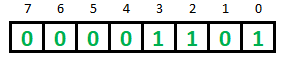
Whenever we are writing or reading from a slave device, we are working with the data stored in registers. Think of a register as 8 slots holding a 1 or a 0, as shown in the image below.
Just like the device addresses explained earlier, register addresses will also be written in hexadecimal most of the time. To get a value stored in a register located at 0x01, this address must be sent first. After the slave acknowledges the address, it sends the register's content immediately. Then if the master acknowledges (ACK), the slave sends the content of the next register, in this example, register 0x02, and it keeps sending the data of each following register up until the master not-acknowledges (NACK).
Writing to Slave Devices
Writing is just slightly different than reading, and it usually requires an extra step since sometimes we want to change a specific bit of a register, not all 8 bits. For instance, if we wanted to set a bit (change to 1) at the bit number 4 and clear a bit (change to 0) at the bit number 3 in the register shown above, we would have to write a register value of (00010101)2 to the address 0x01. In order to do that, we first have to read the current value of the register (all 8 bits) and then modify just the two bits at locations 3 and 4. This is usually done with bitwise operators that depend on the programming language that is used. Here I will show you how this is done in C, and I expect that you know some basic Boolean algebra to figure the logic out (and logic stuff is fun to figure out).
Setting a bit at the location x:
registerData |= 1 << x;
Clearing a bit at the location x:
registerData &= ~(1 << x);
Toggling a bit at the location x:
registerData ^= 1 << x;
Another important thing to note about writing to the slave is that you cannot use the same fancy thing about writing to each consecutive register as when reading from the slave. When writing to a register, we first send a start condition, the slave's address, the direction bit, the register's address that we want to write to, and then the data, followed by the stop condition. If we want to write data to the next register, we must repeat the whole sequence using the new register's address.
Now let's do some examples with the real hardware. I recommend you go through all of the examples even if you don't use the specific device or the language used in the example. Focus on the general information related to I2C that I provide since you might find it useful later in the future. In the first example, with the Arduino Uno, I will also show the oscilloscope output and analyze it.
Arduino Example
For this example, I will use the MPU6050 IMU as well since this is a chip I work most often with, and I think it's simple enough to use it for an introductory I2C example. The MPU6050 operates on 3.3 V, but the board has a voltage regulator, so it will also work by connecting it to 5 V. The schematic for this example is shown below:
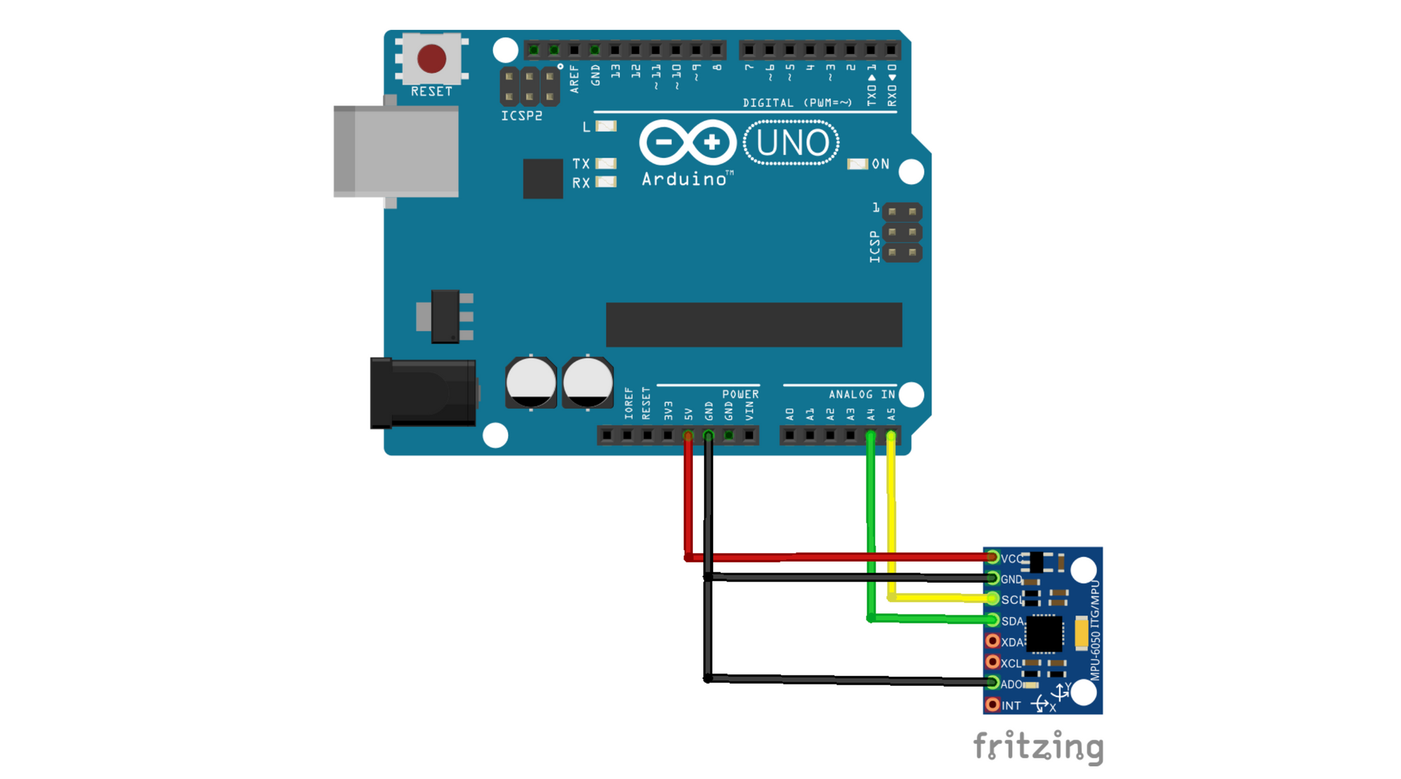
The Vcc pin on the MPU6050 is connected to 5 V on the Arduino. Grounds (GND) are connected together. SCL and SDA pins on the MPU6050 are connected to SCL and SDA on the Arduino, SCL is connected to pin A5, and SDA is to pin A4. AD0 pin on the MPU6050 is connected to the ground; the AD0 pin is the "device address select" pin, since if connected to the ground, MPU6050's address is (68)16; if connected to Vcc, its address is (69)16. This makes it possible to use two MPU6050s on the same I2C bus.
With the MPU6050, we can measure acceleration and angular rates in three axes (X, Y, and Z), but for simplicity, I will read only acceleration in the X direction. All of the measurements on the IMU are 16 bits long; hence they are stored in two separate registers that have to be read separately and combined into one 16-bit variable on the Arduino.
In the future, I should add an example with the ATmega328P, where I will go more into lower-level details on how I2C works. Still, in this example, with the Arduino Uno, I will keep it a bit simpler and use Arduino's "Wire.h" library, which is written specifically for I2C communication. First, I will show the code and then explain it.
#include<Wire.h>

#define MPU6050_ADDRESS 0x68 // MPU Address
#define MPU6050_RA_ACCEL_XOUT_H 0x3B
#define MPU6050_RA_ACCEL_XOUT_L 0x3C
#define MPU6050_RA_PWR_MGMT_1 0x6B

int16_t AcX;

void setup(){
  Wire.begin(); //  join the I2C bus as a master
  Wire.beginTransmission(MPU6050_ADDRESS); // begin transmission to MPU6050 (Slave)
  Wire.write(MPU6050_RA_PWR_MGMT_1); // queue the power management register address
  Wire.write(1); // queue the register value for the clock source to X-gyro (performs slightly better than the default 8 MHz)
  Wire.endTransmission(true); // transmits the addresses queued with Wire.write() and ends the transmission initiated by Wire.beginTransmission()
  Serial.begin(9600); // initiate a serial communication at 9600 bits/s
}
void loop(){
  Wire.beginTransmission(MPU6050_ADDRESS); // begin transmission to MPU6050 (Slave)
  Wire.write(MPU6050_RA_ACCEL_XOUT_H);  // queue the ACCEL_XOUT_H register
  Wire.endTransmission(false); // send the queued ACCEL_XOUT_H register and send repeated start the "writing to slave" transmission
  Wire.requestFrom(MPU6050_ADDRESS,2,true);  // request 2 bytes from the slave
  AcX=Wire.read()<<8|Wire.read();  // combine data from both registers, the 0x3B (ACCEL_XOUT_H) & 0x3C (ACCEL_XOUT_L) into one 16-bit variable
  Serial.print("AcX = "); Serial.println(AcX); // send the measurement via serial
  delay(10); // 10 ms delay
}
I will assume that you know the basics of C or Arduino dialect, so I won't go into details on how to include a library, how to declare a variable, or what setup() and loop() functions are.
Wire.begin(); sets up the chip for the I2C communications and joins the I2C bus as a master. (If we wanted the Arduino to be a slave device, we would pass a desired I2C address to the begin method.)
Wire.beginTransmission(MPU6050_ADDRESS); does what is says, it begins the transmission with the slave device, in this case, the MPU6050 with the address 0x68 as defined with the MPU6050_ADDRESS macro.
The following two lines: Wire.write(MPU6050_RA_PWR_MGMT_1); and Wire.write(1); queue ("store") the bytes to be sent to the slave device when Wire.endTransmission(true) is called. The input argument for the endTransmission method specifies whether to end the transmission with a Stop or Repeated Start condition. The repeated start is used when we want to send a command to a device and then read the response right away. This keeps the I2C bus busy, so another master on the bus cannot interrupt the transmission. The MPU6050_RA_PWR_MGMT_1 register sets up the clock source that drives the IMU. I don't want to go into details here; I will write another post about the MPU6050. For now, remember that by setting the MPU6050_RA_PWR_MGMT_1 register to 0b00000000 (0), the MPU6050 will use its internal 8 MHz clock; by setting the register to 0b00000001 (1), it will use the X-gyroscopes clock, which was determined to be a bit more stable than the default clock. An important thing to remember about how Arduino's "Wire.h" library works is that it queues the bytes we want to send and sends all of them when the endTransmission method is called. A queue is a FIFO (First In First Out) data structure, meaning whatever we queue first will be sent first. Let's show how this works by reviewing the code inside the loop() function.
Wire.beginTransmission(MPU6050_ADDRESS);-queue the 7-bit MPU6050 address - 0b1101000Wire.write(MPU6050_RA_ACCEL_XOUT_H);-queue a 0 (write to slave) bit after the address and the register address byte we want to send to the slaveWire.endTransmission(false);-send the two bytes queue above and send a repeated start instead of a stop condition because we want to receive data from the slaveWire.requestFrom(MPU6050_ADDRESS,2,true);-send the 7-bit MPU6050 address, the 1 (read from slave) bit, and let's prepare to read two bytes from the slave. This means that after the first byte is received, the master acknowledges (ACK) and not-acknowledges (NACK) after it receives the second byte. The third argument, "true", let's the master know that we want to stop the communication after we receive both bytes.AcX=Wire.read()<<8|Wire.read();-with the methodWire.read()we read each byte (8-bits) of the 16-bit accelerometer measurement separately and store it in a 16-bit variable AcX. Below is a detailed explanation of this line of code.
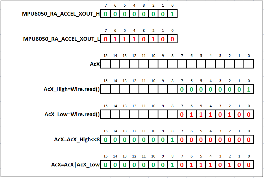
The MPU6050 IMU uses a 16-bit analog-to-digital converter (ADC) for digitizing sensor outputs, so all the sensor readings are 16-bit signed integer values (two's complement format), but it stores the number in two 8-bit registers. The most significant byte (the high byte) is stored in one register, while the other, the least significant byte (the low byte), is stored in another register. For convenience, the MPU6050 (as well as most of the other sensor devices) holds the high byte of the sensor measurement one register before the register that holds the low byte. For instance, the X-Accelerometer high byte is stored at the address 0x3B, while the low byte is stored at 0x3C, so by taking advantage of the ACK and NACK bits, we can receive both bytes one after another. The line AcX=Wire.read()<<8|Wire.read(); reads both the high and the low byte one after another and does some bitwise operations to store them in the 16-bit variable AcX. These operations can also be written in multiple lines of code for better clarity, such as:
  AcX_High = Wire.read();
  AcX_Low = Wire.read();
  AcX = AcX_High<<8;
  AcX = AcX|AcX_Low;
The first line stores the high byte to AcX_High 16-bit signed variable (int16_t), the second line does the same with the low byte and stores it to AcX_Low, the third line shifts the high byte 8-bits to the left with the bit-shift operator (left: <<, right: >>), the fourth line performs the bitwise OR operation with the AcX variable containing the shifted high byte and the AcX_Low variable containing the low byte. The bitwise OR does the OR operation between each bit. Below is a graphical representation of these operations.
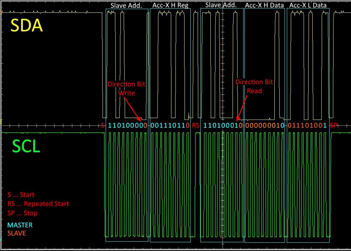
It's important to mention that the endTransmission method sends what is stored (queued) in a queue, it does not send all of it at once, but it sends the next byte only if it received an acknowledgment (ACK) from the slave. To ensure that everything I wrote here is true, look at the output from the oscilloscope connected to the SDA and SCL while the above program was running. I will leave it to you to make sense of the oscilloscope output.
I think it is important to write a few programs "from scratch" as we did in this example to gain a deeper understanding, but for larger programs, I would recommend using the i2cdevlib by jrowberg. The i2cdev is a large library package with many contributors. It takes has many useful functions, for instance, a function for writing only a specific bit, etc. The package also contains libraries for many i2c devices. I would encourage you to go through the source code of the I2Cdev.cpp for the Arduino and try to understand what is happening.
Raspberry Pi Example
On the Raspberry Pi, you can use I2C with a language of your choice (Python, C, C++, Java, etc.), but here I will show an example with Python since I think this is a good place to start. If you feel like using another language, then a solid understanding of the principles of I2C should be enough to figure out the rest.
I assume you are using Raspberry Pi 3 with the Raspbian operating system and already have Python 2 or 3 installed. To follow this tutorial, install the following packages:
sudo apt-get install -y python-smbus
sudo apt-get install -y i2c-tools
sudo apt-get install build-essential libi2c-dev i2c-tools python-dev libffi-dev
SMBus (System Management Bus) is a two-wire protocol that can be considered a subset of I2C and is very common in computer motherboards. The principle is pretty much the same as in I2C, but some differences should be considered. I will not go into detail here, but you should familiarize yourself if you will be working on a project where I2C and SMBus devices share the same bus. You can find more information in the SMBus documentation.
After all the packages have been installed correctly, you have to enable the I2C interface by typing raspi-config, then go to Interfacing Options, where you can enable I2C. More on configuring I2C can be found on Adafruit and at Sparkfun.
To connect the MPU6050 to Raspberry Pi you can reference the following diagram:
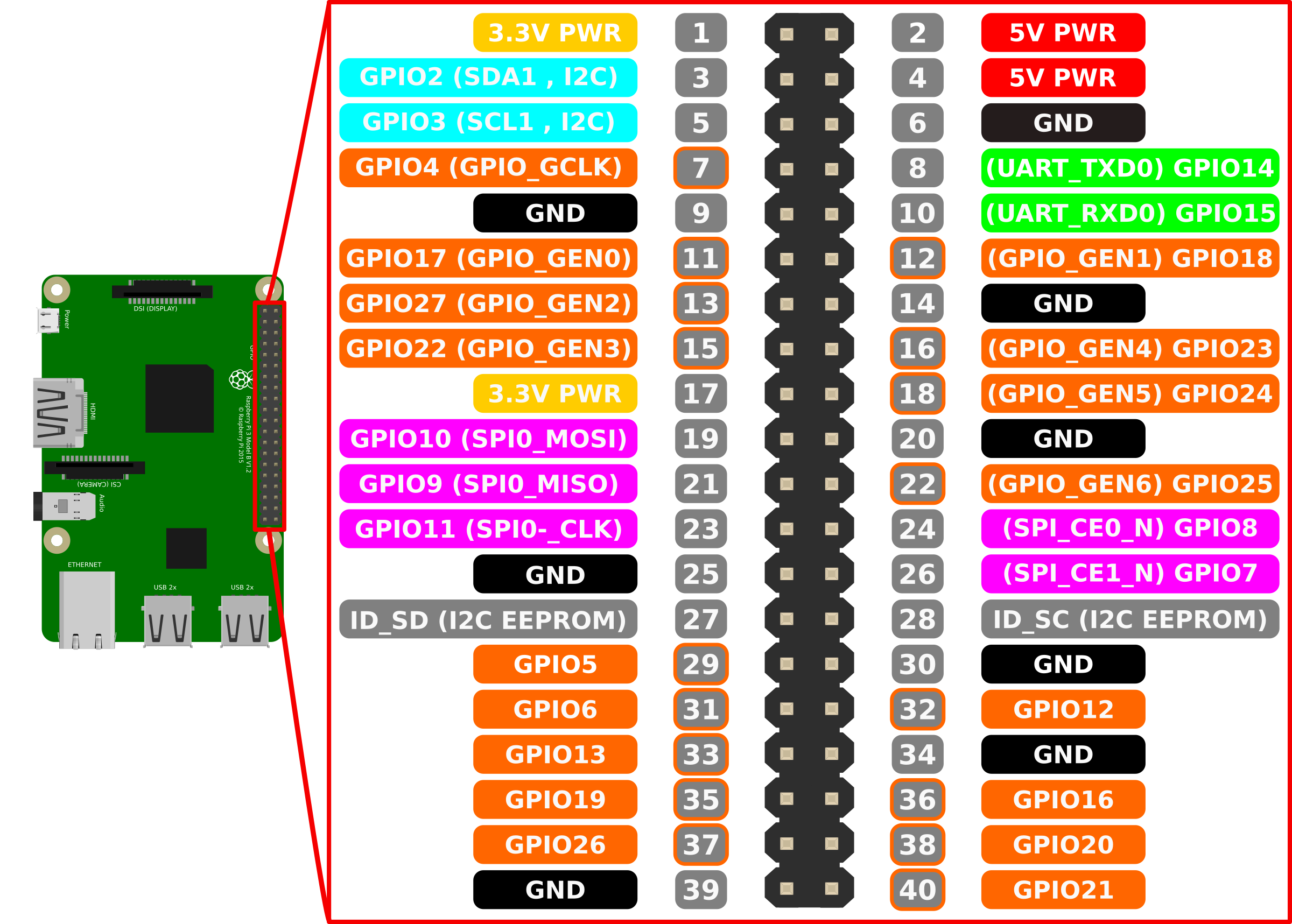
As you can see on the gpio diagram above, you need to connect SDA from MPU6050 to pin 3 and SCL to pin 5. The ground can be connected to any of the GND pins. You can power the MPU6050 from any of the 3.3 V or 5 V gpio pins on the Pi, since the MPU6050 converts the input voltage to 3.3 V anyway, but since the chip runs on 3.3 V, you might as well use this voltage level.
Now that all the packages are installed, and everything is hooked up let's check if the RPi detects the MPU6050 by running the command i2cdetect -y 1. The output of the command should look similar to this:
     0  1  2  3  4  5  6  7  8  9  a  b  c  d  e  f
00:          -- -- -- -- -- -- -- -- -- -- -- -- --
10: -- -- -- -- -- -- -- -- -- -- -- -- -- -- -- --
20: -- -- -- -- -- -- -- -- -- -- -- -- -- -- -- --
30: -- -- -- -- -- -- -- -- -- -- -- -- -- -- -- --
40: -- -- -- -- -- -- -- -- -- -- -- -- -- -- -- --
50: -- -- -- -- -- -- -- -- -- -- -- -- -- -- -- --
60: -- -- -- -- -- -- -- -- 68 -- -- -- -- -- -- --
70: -- -- -- -- -- -- -- --
Here you can see all the devices that were detected on the bus. In my case, only one device with an address 68 was detected. As you should know from the example above, this is the address of the MPU6050.
Now let's start by creating a Python file named i2cTutorial.py. Just like in the example with the Arduino, I will first show you the code and then go through it line by line.
import smbus
import time

bus = smbus.SMBus(1) # set 1 for /dev/i2c-1 I2C1

DEVICE_ADDRESS = 0x68 # MPU6050 7-bit address
PWR_MGMT_1 = 0x6B # power management register address
ACCEL_XOUT_H = 0x3B # accelerometer high byte register address

# Write a single register to set to clock source to X-gyro
bus.write_byte_data(DEVICE_ADDRESS, PWR_MGMT_1, 1)

while True:
    receivedBlock = bus.read_i2c_block_data(DEVICE_ADDRESS, ACCEL_XOUT_H, 2)

    if receivedBlock[0] > 127:
    	receivedBlock[0] = (256-receivedBlock[0])*(-1)

    accelX = (receivedBlock[0]<<8)|receivedBlock[1]

    print("AcX = " + accelX)
    time.sleep(0.01)
Before explaining the code, I will briefly mention information about I2C-0 and I2C-1. If you look at the pinout diagram above, you will see that pins 3 and 5 are labeled SDA1 and SCL1 respectively. The number 1 at the end means that these two lines belong to the I2C-1 bus. Pins 27 and 28 are also I2C data and clock lines, but they are specifically used for talking to EEPROM chips and nothing else (unless you reconfigure your Pi). It is commonly used to initialize Raspberry Pi hats at startup with some data stored on an EEPROM chip. More info on this can be found here.
The first two lines in the code import smbus and import time are used to import the smbus module, and the time module I used only to add a short delay in the loop. Next, we have to create a bus object from the smbus class: bus = smbus.SMBus(1). Argument 1 means we will use the I2C-1, as described in the previous paragraph. Following the first 3 lines are just variables containing the MPU6050 7-bit address, the power management 1 register address, and the high byte of the accelerometer reading address. Just like in the example with the Arduino, I set the clock source of the MPU6050 to X-gyro by writing a single byte, a number 110, or 0b00000001 to the power management 1 register with the method bus.write_byte_data(DEVICE_ADDRESS, PWR_MGMT_1, 1)
Then I created an infinite while loop without an option to terminate it, so ctr+c has to be pressed to terminate the script (too lazy). The method receivedBlock = bus.read_i2c_block_data(DEVICE_ADDRESS, ACCEL_XOUT_H, 2) reads 2 bytes, the high and the low byte of the acceleration in the X-direction. The read_i2c_block_data() method returns an array with as many elements as the bytes that it received. The last part of the code is just some bit twiddling to get a 16-bit signed integer value of the reading, similar to what was done in the Arduino example. As you recall, the MPU6050 sends the high byte number in 2's complement format, where it can range from -128 to 127. Only two bytes were requested from the device in this example, so the receivedBlock becomes a two-element array with the value at the element at the index [0] corresponding to the high byte of the accelerometer-X reading and the element at the index [1] to the low byte. If an 8-bit 2's complement value is larger than 127=0b01111111, it is, in fact, a negative number, and it has to be subtracted from 256=0b11111111 and then inverted bit by bit (complement) to get the corresponding negative number. As the last step, the two received bytes are packed into a 16-bit number by shifting the high byte 8 bits to the left (same as in the Arduino example) with the accelX = (receivedBlock[0]<<8)|receivedBlock[1]. In the end, a simple print statement displays the readings and a line for the 10 ms delay.
ATmega328 is coming soon (or not, as this is an old post), but if you need help, please feel free to contact me. Additionally, look into the i2cdev library.
Sources (recommended reading)
For any suggestions or improvements, please feel free to contact me.